Messages Flow Mapping
This is a guide to configuring the message flow in Agents by mapping the data types.
To understand more about message flows first read about Skills and Service Messages.
Message flows connect service messages and skills.
In the Agent Composer message flows are represented as follows:
- Message flows that represent inputs to Skills are represented by blue lines.
- Message flows that represent outputs to Skills are represented by green lines.
In SENSA Fabric data flows the following ways:
- Inputs (from the Inputs panel) to Skills
- Skills to Skills (through the Synapse panel)
- Skills to Outputs (through the Outputs panel)
All data that passes through an Agent flows in the form of structured messages. A message is an ordered list of field names and data types plus a set of rules and metadata.
To connect components the message structure from the source must be mapped to the message structure of the destination so that the data types match. The field names may or may not match.
Junctions are equipped with Data Quality Indicators. These symbols show the health of the data flow through that junction and provide the mapping interface.
Mapping solves the problem of matching the data type and field name parameters of data passing through the junctions.
Data Quality Indicator types
- Green indicator - The data field names and types in the source and destination message schemas match; messages will be delivered/received successfully without additional mapping.
- Half-yellow indicator - The data types in the source and destination message schemas match, but the field names are different; messages should be delivered/received successfully without additional mapping, but you can review the mapping to ensure fields are mapped appropriately by clicking on the indicator.
- Red indicator - The source and destination message schemas do not match; mapping is necessary. Without mapping, passing messages from the source to the destination will fail.
Click the indicator to open the mapping dialog.
How data flow is configured
Data flow configuration is accomplished in three distinct steps.
Connect each Skill in the agent to the data message inputs and outputs. Inputs and outputs are joined to Skill actions by selecting the Skill action and then clicking on all of the inputs and outputs for the action in the Inputs panel, Outputs panel, and Synapse panel. For details go to Manage Inputs and Outputs
Create a message flow from Skills to required Data Sources.
Click on the data quality indicator at each junction to map the message flows. Data types between the two entities at the junction must match exactly. The names of the fields may or may not match to allow healthy data flow.
Create message flows paths
Prerequisites
- The Agent record must be created.
- Skills must be added to the Agent.
- Inputs and Outputs (Service Messages) must be added to the Agent.
Steps
- Click on a Skill to select it.
- The compatible inputs and outputs are displayed in a green circle with a plus sign icon beside them.
- Click a corresponding plus icon from the input panel, the output panel, or the synapse board.
- The path will be created when the Skill definition contains only one action. When the Skill definition contains multiple actions, they are displayed above the Skill bubble.
- Click the icon beside the Skill action to connect it to the selected input or output.
- If you want to add paths to the Skill continue to select inputs and outputs from the panels and synapse board.
OR
- Click on an input, output or synapse to select the component.
- Skills that have compatible actions display a corresponding plus icon.
- Click the Skill to create the path. If only one action is defined in the Skill, the path is generated. If multiple actions are defined, they are displayed above the Skill bubble.
- Click the icon beside the Skill action that you want to connect to.
- If you want to connect the source to additional Skills, click another Skill. You do not need to select the source again.
After the paths are generated, you must map junctions where parameter types do not match. The Data Quality Indicator bubbles are red where data mapping is needed.
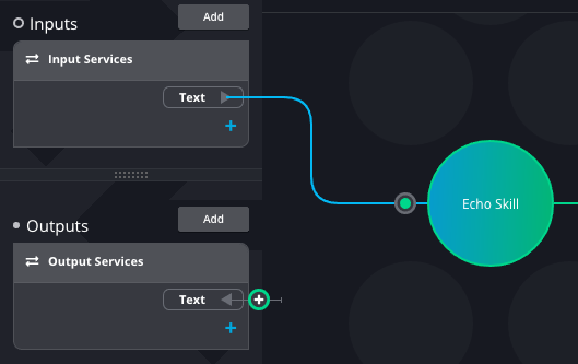
The example below shows an input and output service and the type of each: Text.
The selected Skill is connected to the input service, the icon next to the output service indicates that the
service provides the message type that the Skill requires: the two components
can be connected.
Mapping data
Data Quality Indicators provide a visual indicator of the mapping health of the message flows through a junction as well as access to the mapping interface for the junction. (see descriptions above)
Open the data mapping dialog at any junction by clicking the Data Quality Indicator.
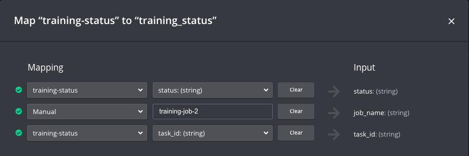
For each field in the destination message schema (listed on the right under the Input heading), select a mapping source and field value. There are two Mapping options:
Select the data source you are connected to and select a field/type from the source message schema.
Select Manual to enter a static field value to be used every time a message is sent through the connection you are mapping.
Click Update to save the mapping changes.
The example mapping below shows two fields mapped from the data source and one field with a Manual entry.
All of the input and output data types must match for the connection to run successfully in the Agent.